
The first step in selecting an industrial robot is to define the production task and technical requirements precisely. These requirements identify the possible robot types, whose suitability must then be assessed as part of the complete application, together with the gripper, process equipment and control system. The same robot may perform exceptionally well in a material handling operation yet be unsuitable for assembling a workpiece of a similar size. The difference often lies in the gripping method, the required tool pose or the target cycle time.
Starting with the application requirements, this article introduces the main robot types and the technical factors that guide selection. An electronics test cell illustrates when two fixed robots can be replaced by a single robot on an external linear axis, and how this affects capital expenditure. Common misconceptions and a short checklist then help bring the selection process to a conclusion.
Defining the application requirements
Selection should begin with a description of the workpiece and the production process. This should cover the range of dimensions and masses, variation in pickup position, required gripping operations, target output and available space. The product variants to be handled and the expected changeover requirements must also be defined.
The surrounding process must be examined alongside the robot motion. Inconsistent part presentation, unreliable gripping or long waits for process equipment can limit the performance of the entire system. Selecting peripheral equipment and conducting an initial feasibility assessment are therefore integral to robot selection.
Kinematic classification of industrial robots
A robot’s mechanical structure determines its available movements and the shape of its workspace. In a serial structure, links and joints connect sequentially from the base to the tool. In a parallel structure, several mechanical chains connect the moving platform to the base; the delta robot is a widely used industrial example.
Axis motion is also described using letters: R denotes rotary motion and T denotes linear motion; international literature also uses P for the latter. For serial robots, both the motion types of the first three positioning axes and their spatial arrangement are important. The appropriate configuration must therefore be selected according to its actual motion capabilities and workspace.
Main robot types used in industry
The main robot types can be distinguished by their workspaces, motion capabilities and applications. The numerical examples below illustrate the characteristics of particular variants, not the limits of an entire category. Values specified under different measurement conditions cannot be used to rank robots directly.
Cartesian robots
A Cartesian robot has three positioning axes that move linearly at right angles to one another. This TTT structure produces a rectangular workspace whose dimensions can be adjusted through the axis travel lengths. Gantry and cantilever arrangements allow larger areas, machines or conveyors to be served from above.
Typical applications include injection moulding machine tending, loading and unloading, part handling, dispensing and palletising. Their advantages include a straightforward motion system and axis travel lengths that can be adapted to the task. Rotating a workpiece, however, requires an additional rotary unit. For long axes, support structure stiffness and moving mass are particularly important design considerations.
Sizes range from compact benchtop units to gantry robots spanning several machines. Axis travel, payload capacity and the required motion dynamics must be specified together: a larger motion range alone does not guarantee higher production output.
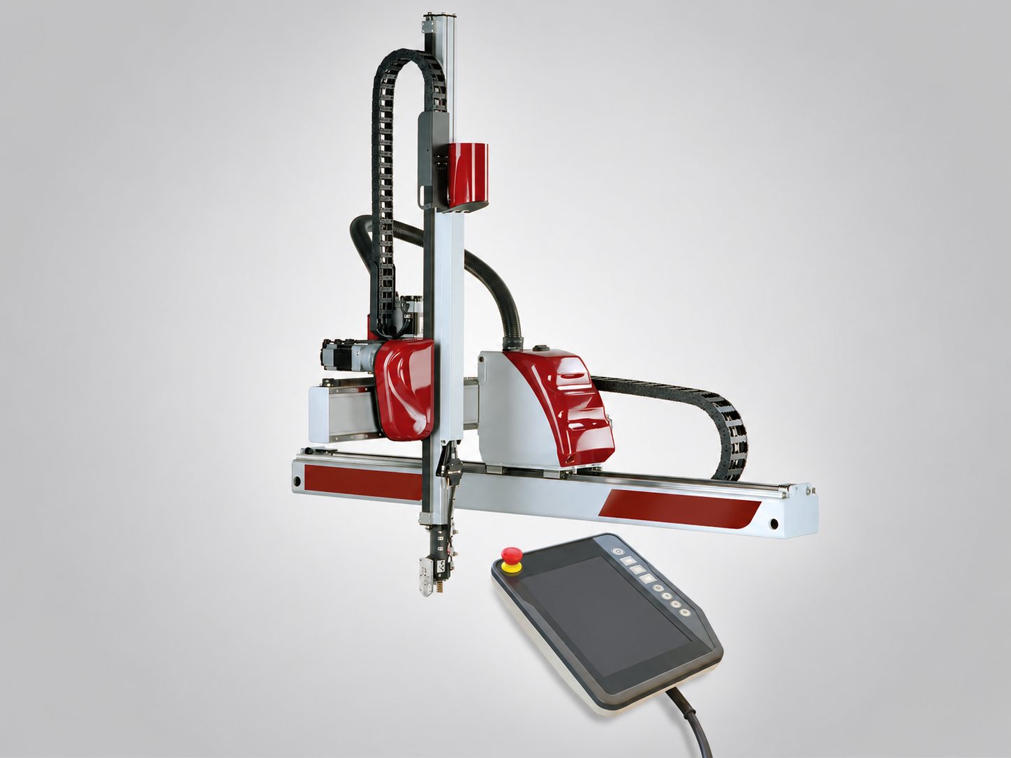
Figure 1 Cartesian industrial robot
SCARA robots
A SCARA robot typically has two arms rotating about parallel vertical axes, a vertical linear axis and an additional axis for rotating the tool. Its basic positioning structure is RRT, and the complete robot generally has four axes. Depending on arm lengths and axis limits, its workspace resembles an annular cylinder.
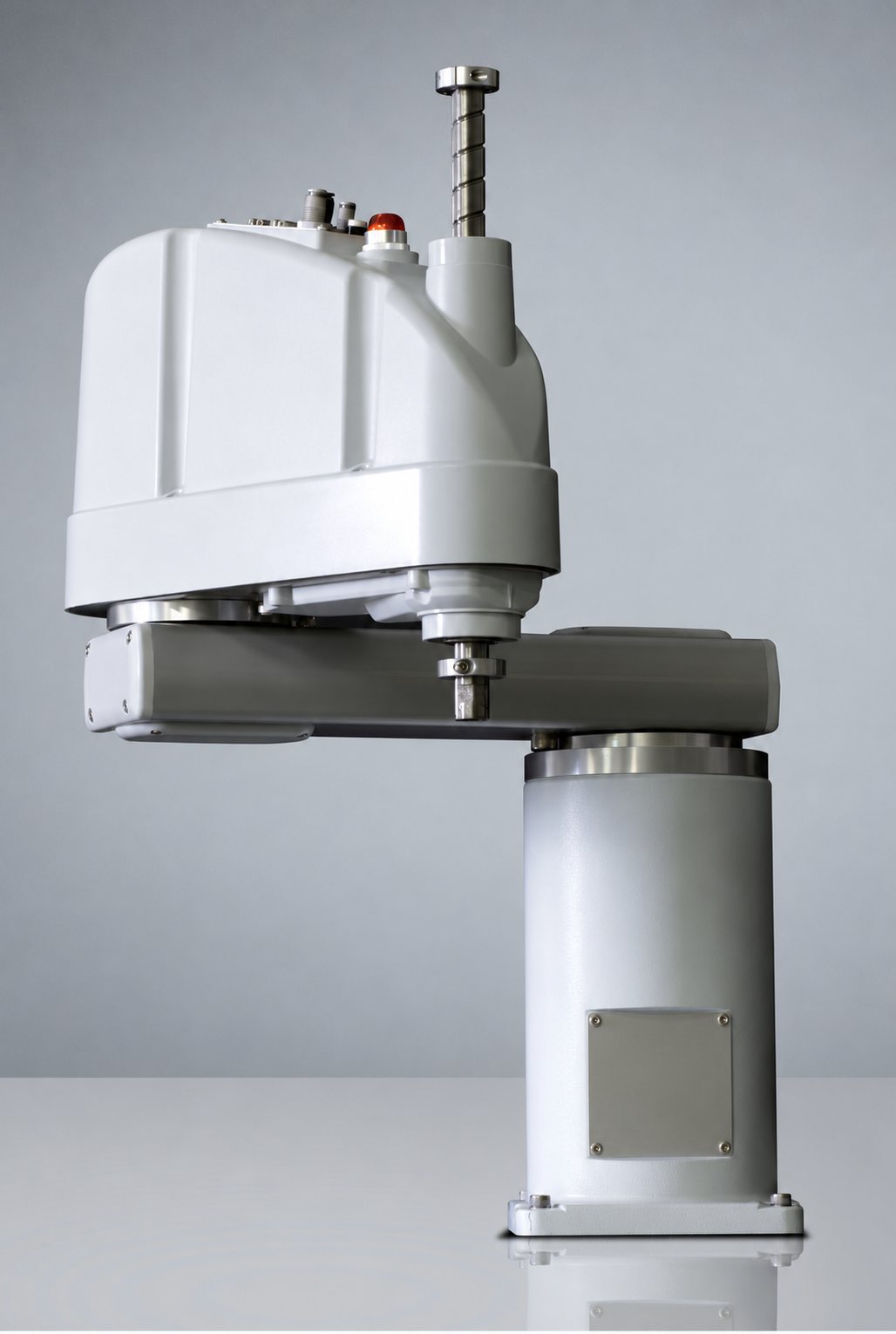
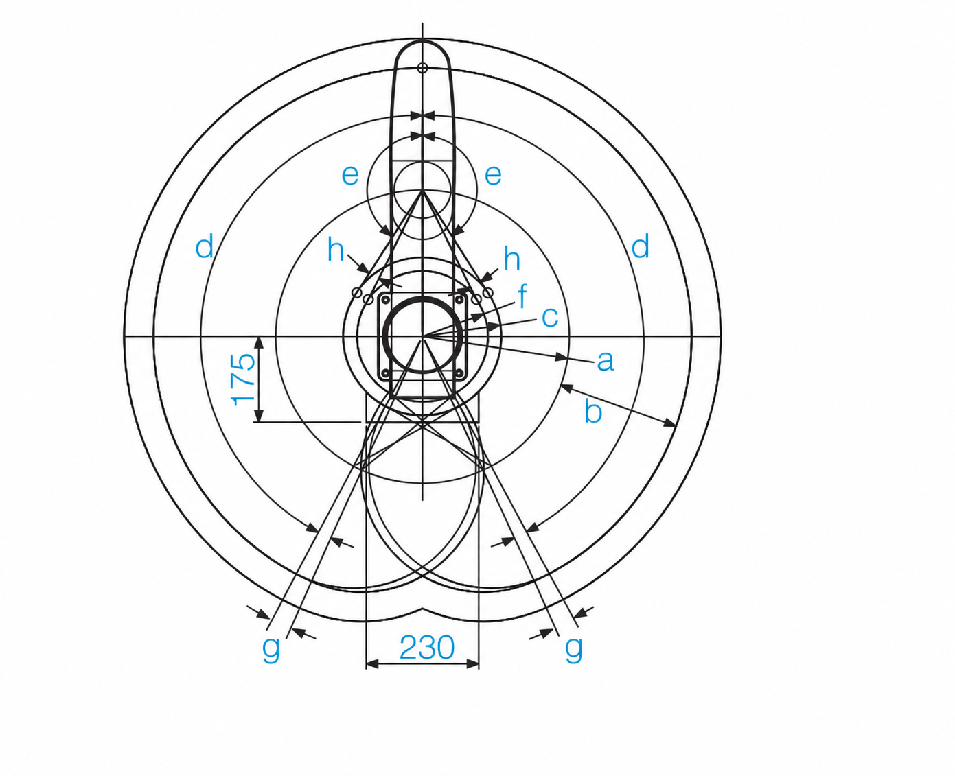
Figure 2 SCARA robot and top view of its workspace
SCARA robots are primarily used for fast horizontal transfers and vertical assembly movements. The term selective compliance in their name means that structural stiffness varies with direction: they are stiffer vertically and more compliant in the horizontal plane. This characteristic alone does not provide force-controlled or safely collaborative operation.
Typical tasks include electronics assembly, screwdriving, vertical insertion, test station tending and loading parts into trays. They are particularly useful when operations can be performed from above and the product does not need to be tilted. For the 550 mm variants in the Epson G6 series, the manufacturer specifies a rated payload of 3 kg and a maximum payload of 6 kg. Repeatability is ±0.015 mm for the combined motion of axes 1 and 2, and ±0.010 mm for the vertical third axis. These are model-specific values from the manual; payload and inertia settings also affect the achievable motion dynamics.
Epson G6 technical specifications
Six-axis articulated robots
The first three main axes of a six-axis articulated robot typically form an RRR structure and primarily position the arm. The remaining three axes orient the tool. Subject to suitable geometry and axis limits, the six axes provide three-dimensional positioning and changes in orientation.
Their workspace is a complex volume with internal and external limits that cannot be described by a single reach value. Actual accessibility depends on arm geometry, self-collision limits, the tool and surrounding equipment. This versatility is especially useful in welding, machine tending, adhesive dispensing, complex material handling and surface treatment.
Available robots range from small-part handlers to models capable of handling heavy workpieces. Both KUKA and FANUC offer articulated robots with a variety of reaches and payload capacities. Payload, accessibility and the required motion dynamics must be evaluated together. Fast point-to-point motion and accurate process path following impose different requirements.
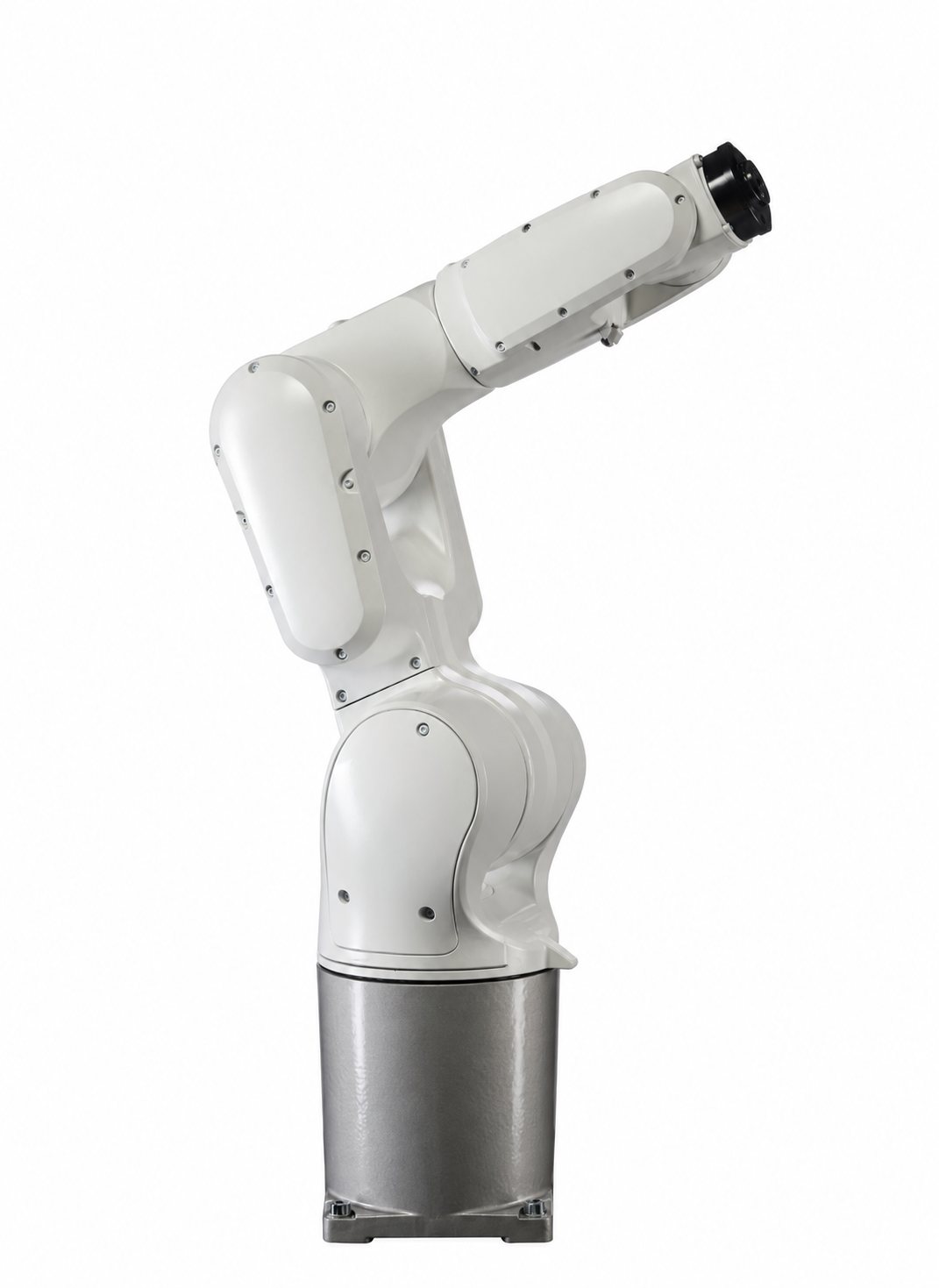
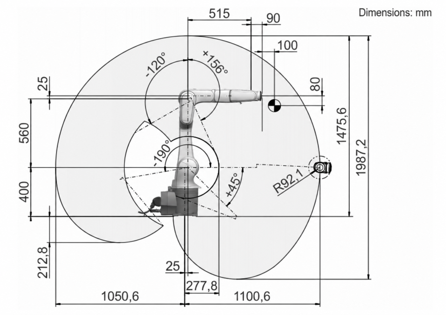
Figure 3 Six-axis industrial robot and its workspace
Six-axis robots with a linear seventh axis
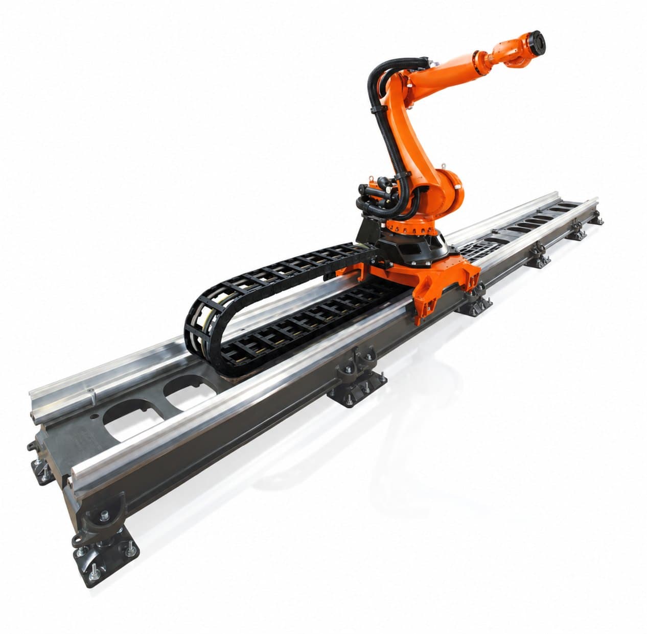
Mounting a six-axis robot on a linear track extends its workspace by moving the robot base. The external axis allows it to serve several workstations, a production line or a long workpiece. Typical applications include machine tending, welding and processing large surfaces. With a suitable control configuration, the linear axis can move in coordination with the robot arm.
This arrangement remains a combination of a six-axis arm and an external linear axis. The robot’s own reach is extended by translating its workspace along the track. The track carriage’s load capacity is not the same as the payload capacity at the robot’s tool flange. The accuracy of the robot and linear unit, their joint calibration, cabling and total motion time must be assessed as a system.
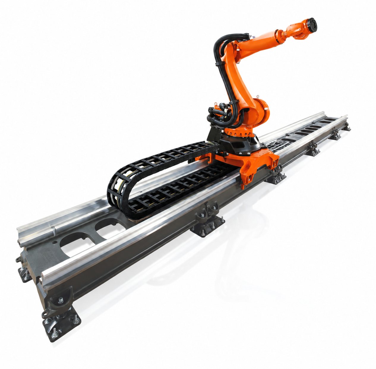
Figure 4 Six-axis industrial robot on an external linear axis
Seven-axis robot arms
An arm with seven rotary joints offers a different capability: the additional axis allows it to change its configuration while maintaining the tool’s position and orientation. This property is known as kinematic redundancy. It can be useful in confined spaces, when reaching around obstacles and in complex assembly tasks. Variants equipped with suitable sensing and control can also perform delicate assembly and force-controlled insertion. These capabilities do not follow from the number of axes alone; the conditions for collaborative operation must also be verified for the complete application.
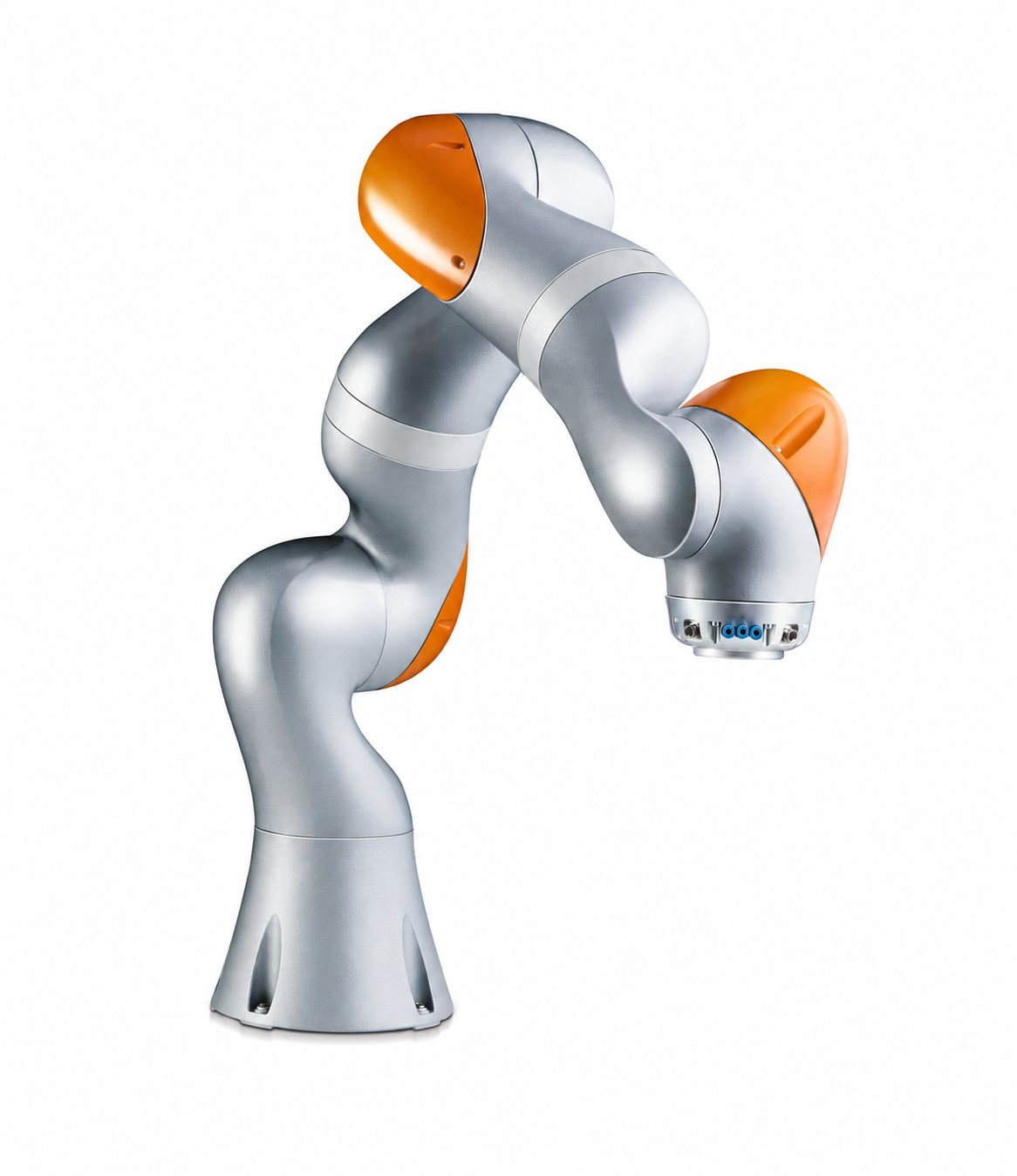
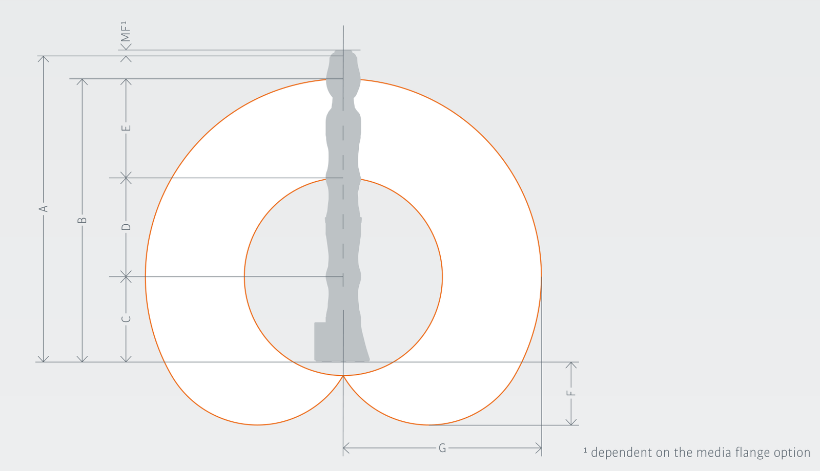
Figure 5 Seven-axis industrial robot and a cross-section of its workspace
Delta robots
A delta robot’s moving platform is connected to its base by several parallel kinematic chains. Many of the drives are located close to the base, helping to minimise moving mass and achieve high acceleration. The workspace is generally accessed from above, with a useful central region and complex boundaries towards its edges.
Delta robots are mainly used for high-speed sorting, packaging and picking from conveyors. Tool orientation capabilities depend on both the number and arrangement of axes; three-, four-, five- and six-axis variants are available. Their high dynamic performance can only be fully used if product detection, conveyor tracking and gripping can keep pace with the required production rate.
The five-axis ABB IRB 365-1.5/1100 delta robot has a payload capacity of 1.5 kg and a nominal workspace diameter of 1,100 mm. The manufacturer specifies pose repeatability of 0.05 mm in testing to ISO 9283, at rated payload and a speed of 1.6 m/s, in the test plane defined by the standard. This does not guarantee the same result at every working point or in every direction of motion. Accessibility, orientation and gentle product handling must be verified for the specific application.
ABB IRB 365 technical specifications
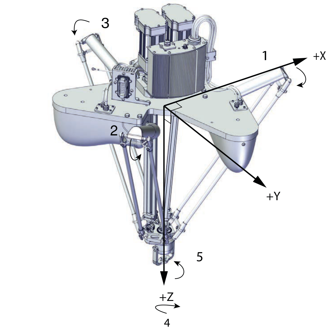
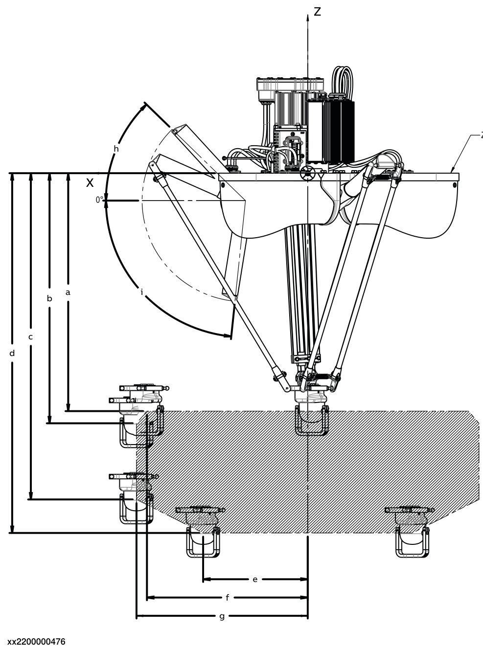
Figure 6 Delta robot and side-view cross-section of its workspace
A practical comparison of robot types
The following table summarises typical selection criteria. More than one configuration may suit a given task; the decision must be based on an assessment of the complete application.
| Robot type | Typical application | Main advantage | Limitation to consider |
|---|---|---|---|
| Cartesian | Machine tending, loading and unloading, dispensing | Axis travel can be adapted to the task. | Rotation requires an additional axis; stiffness is critical for long travel. |
| SCARA | Planar transfers, vertical assembly | Fast motion for operations accessible from above. | The standard four-axis design cannot provide arbitrary spatial orientation. |
| Six-axis articulated | Welding, machine tending, adhesive dispensing | Versatile spatial access and orientation. | Axis limits, singularities and collisions may restrict the path. |
| Six-axis with an external linear axis | Serving several stations or a long workpiece | Moving the robot base extends the workspace. | Track footprint, calibration, cabling and travel time also matter. |
| Seven-joint arm | Assembly in confined spaces, obstacle avoidance | Different arm configurations can achieve the same tool pose. | An additional axis alone does not guarantee force control or collaborative operation. |
| Delta | High-speed sorting, packaging | Low moving mass and high dynamic performance. | Usable workspace, orientation capabilities and gripping may limit the task. |
Key factors in robot selection
Payload capacity and dynamic loading
Payload capacity applies to the total load attached to the tool flange. In addition to the workpiece, this includes the gripper, tool changer, adapters and any accessories moving with them. For example, a 6 kg product, a 3 kg gripper and a 1 kg adapter add up to a total load of 10 kg. The load must be defined for both the empty and loaded gripper and, when handling multiple parts, for every relevant part count.
The description “10 kg robot” alone does not establish the size or shape of the assembly it can move. The permissible load also depends on the position of the combined centre of mass, or centre of gravity, and the moments of inertia. A centre of gravity farther from a rotational axis may increase gravitational torque, while greater inertia increases the torque needed for acceleration and deceleration. The change in allowable mass cannot be described by a single rule proportional to distance: the manufacturer’s limits for centre of gravity, torque and inertia must be checked together.
Rated and maximum payloads are not necessarily the same; the maximum value can only be used under the conditions specified by the manufacturer. A load diagram illustrates the relationship between permissible mass and centre-of-gravity position. In the figure, Lz denotes the centre-of-gravity offset along the flange axis, while Lxy denotes the perpendicular offset. The combined centre of gravity of the complete gripper–workpiece assembly must be checked against the curve for the relevant mass. The diagram shown is an example for one robot variant; sizing must always use the applicable data for the selected model.
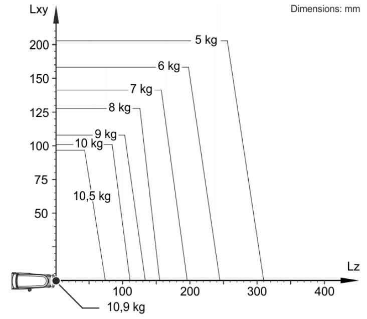
Figure 7 Relationship between payload capacity and centre-of-gravity position for a KUKA robot
Suitability must be checked using the selected robot’s load diagrams and, where necessary, the manufacturer’s sizing software. A centre-of-gravity limit curve alone does not replace an inertia and dynamic analysis. Permissible limits and achievable motion dynamics are model-specific; applying a general percentage margin does not replace this check. The approved load data must also be entered in the robot controller to match the actual tool and product configuration.
A robot with a rated payload of 10 kg is therefore not necessarily suitable for moving a gripper–workpiece assembly weighing 10 kg in total. Suitability must be verified against the manufacturer’s requirements, taking into account the centre of gravity, moments of inertia and required motion dynamics.
Workspace and actual accessibility
The workspace is the volume that a defined reference point on the robot can reach. Reach is one characteristic dimension of this volume; for an articulated robot, it usually means the maximum extension. It does not mean that every point within a complete sphere is accessible with every tool orientation. For delta robots, the nominal dimension is often the workspace diameter; its geometric meaning must always be checked.
The manufacturer’s drawing must also be checked to establish whether the workspace boundary refers to the wrist centre, flange or another reference point. What matters for the application is the position of the tool’s designated working point, the TCP (Tool Centre Point), and the tool orientation. In addition to the pickup and placement poses, the complete approach and departure paths must be examined, accounting for the space required by the arm, gripper, cable package and surrounding machines.
The same tool position and orientation may be reached with several robot configurations, meaning different combinations of joint positions. Alongside axis limits, regions around singularities must also be checked. These are kinematic configurations near which even small tool movements in certain directions may require very high axis speeds. Suitable endpoints alone therefore do not establish that the entire operation can be performed.
Cycle time and production output
Cycle time describes the time required for the complete sequence of operations. It includes approach, gripping and grip verification, transfer, release, and any waiting or synchronisation with the process and other equipment. Operations that can run in parallel must be accounted for according to the actual control sequence.
Maximum axis speeds and the manufacturer’s test cycle alone are insufficient to assess application performance. During short moves, the robot often never reaches maximum speed: acceleration, deceleration and settling time at the target position dominate. Gripper stiffness, product stability and mass distribution therefore directly affect cycle time. The programmed path also matters. Where the process permits, blending between path segments can reduce the number of stops. However, this causes the path to deviate from the original corner point and must remain within the permitted path deviation.
Manufacturers’ test cycles apply to a specified motion path and payload. For example, the result for a 25/305/25 mm test move is not the time required for a complete process operation. The actual task must be simulated or tested using the real positions, payload, gripping times and waits.
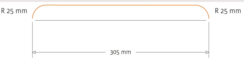
Figure 8 Path of a 25/305/25 mm test move
For production, the decisive measure is the actual number of good parts produced. As an illustration, a six-second cell cycle with one product per cycle gives a theoretical capacity of 600 parts per hour. If availability during planned production time is 90%, the operating performance factor is 95% and the proportion of good parts is 98%, expected output is 600 × 0.90 × 0.95 × 0.98 ≈ 503 good parts per hour.
In this example, availability accounts for downtime, the performance factor accounts for reduced operating speed and minor stops, and the quality factor accounts for nonconforming parts. Each loss must be counted only once. These values are assumptions; actual data must be established through production measurements or agreed acceptance requirements. The aim is to increase the output of the entire production process in terms of good parts.
Accuracy and process suitability
Repeatability, also commonly called repeat positioning accuracy, describes the spread of positions and orientations achieved when a robot returns to the same commanded pose. Absolute positioning accuracy describes the difference between the commanded and actual position, while path accuracy describes the geometric deviation of the path followed during motion. These are different performance characteristics and must be interpreted together with their measurement conditions.
The distinction matters because of the process: taught pickup points may require different capabilities from positioning based on external coordinates or continuous adhesive dispensing. The fixture, product position, gripper, TCP definition and calibration all contribute to the overall process error. For tasks involving machining forces, the stiffness of the robot and workholding, and the deflection caused by those forces, must also be assessed.
In the figure, A denotes the commanded pose and B the mean of the achieved poses; AP illustrates positioning error and RP repeatability. The drawing on the right shows the deviation between the commanded and actual paths, together with the spread of repeated paths.
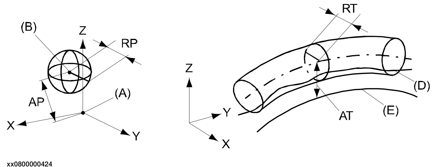
Figure 9 Positioning accuracy, repeatability and path characteristics
Mounting arrangement and support structure
Whether a robot can be mounted on the floor, wall or ceiling depends on the specific variant. Permitted orientations must be checked in the manufacturer’s documentation, taking account of load and lubrication conditions and the necessary controller settings. The ability to attach the robot mechanically does not, by itself, establish that it can operate in that orientation.
The support structure must withstand the forces and torques generated during movement and stopping. Insufficient static stiffness can cause deflection, while unfavourable dynamic behaviour can cause vibration and longer settling times. Both must therefore be considered in the design, using the load data supplied by the manufacturer.
Special environmental requirements
Environmental suitability must be assessed against the actual exposure: dust, moisture, cleaning agents, temperature and process contamination may require different solutions. An IP rating alone does not establish chemical resistance, cleanroom suitability or hygienic design. The robot arm, wrist and control cabinet may have different protection ratings and permissible operating environments.
In a cleanroom, the robot’s particle emissions and the compliance of the complete installation with the required cleanroom class are important. Food-industry applications may require an easy-to-clean design, suitable lubricants and resistance to washdown procedures. Direct product contact and handling sealed packages impose different requirements.
Within healthcare applications, manufacturing medical devices, laboratory automation and direct patient care must be distinguished: suitability for industrial use does not establish suitability for the latter. In potentially explosive atmospheres, a verified design appropriate to the zone and the substances present is required. The suitability of the gripper and other installed units must be assessed alongside that of the robot.
Safety concept and collaborative applications
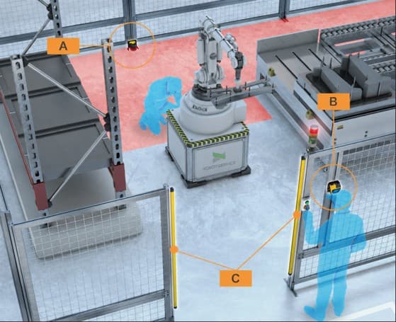
The possibility of collaborative operation must be considered separately from the robot’s kinematic classification. Alongside its built-in safety functions, the complete motion, gripper, workpiece and process hazards must be assessed. The necessary protective measures must be determined through a risk assessment of the complete application.
The safety solution also affects production output and space requirements. Material loading, workpiece removal, troubleshooting and maintenance must be examined, including the interruptions they cause. The target cycle time must be verified with the necessary speed limitations and protective stops taken into account.
Related reading: Collaborative robots and machine safety
Control and integration into the production system
Communication requirements must be defined in terms of specific interfaces and functions. An Ethernet port alone does not, for example, establish support for a particular industrial protocol, communication role or safety communication. The quotation must be checked for the necessary hardware, software options and licences.
Integration may also include vision-based position correction, force sensing, conveyor tracking and external axis control. Beyond the data connection, these functions require coordinated reference frames, calibration, response times and error handling. Operation of the selected solution must also match the skills of the plant personnel and the support available.
Verifying the selection
Before the final decision, the robot must be evaluated in a model of the complete cell or a test setup. Verifying payload suitability, all required tool poses, collision-free paths and the application-specific cycle time together provides a sound basis for procurement. The reliability of a simulation depends on the accuracy of its input data and the level of detail in the model.
Physical trials are advisable where gripping or process steps remain uncertain. Measurable acceptance requirements should be defined at this stage: which product variants, payloads, cycle times and quality criteria will be used to accept the system. This links the selection outcome to a set of requirements that can later be verified.
Case study of tending four testers
The task and the two concepts
In a completed project, Robot-Service automated end-of-line testing for an electronics manufacturer. The task was to pick up the product, tend four sequential test machines and discharge the finished product, with a required output interval of 48 seconds. Nonconforming parts had to be placed on a separate reject conveyor. During design, we examined two concepts and simulated both. The solution ultimately implemented used one robot and an external linear axis. The customer is not named; the economic comparison presents equipment requirements, implementation effort and relative capital expenditure.
In the two-robot concept, the first fixed robot was assigned to the infeed and the first two testers, after which it would place the product in an intermediate transfer nest. The second robot would pick up the part from this nest, exchange parts in the third and fourth testers, and place the finished product at the output point. The concept required two grippers and two reject conveyors because a shared reject conveyor could not be reached from both robot workspaces.
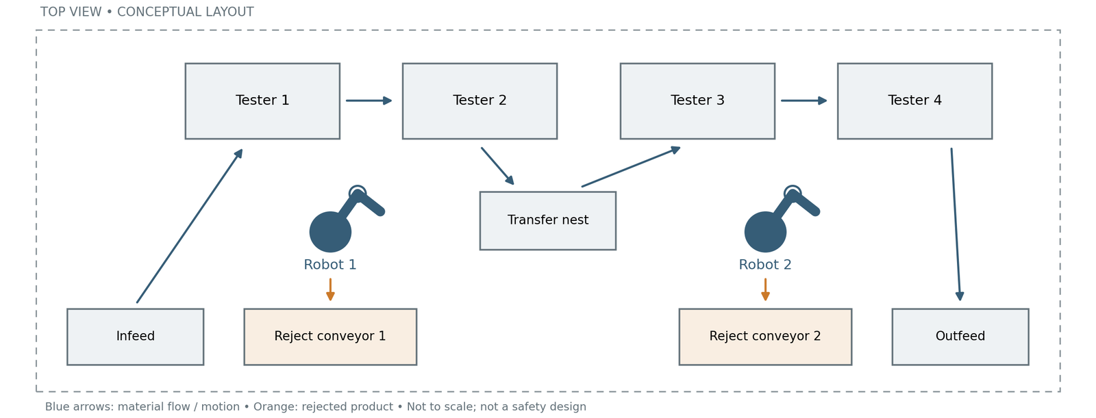
Figure 10 Two fixed robots with four testers and an intermediate transfer nest
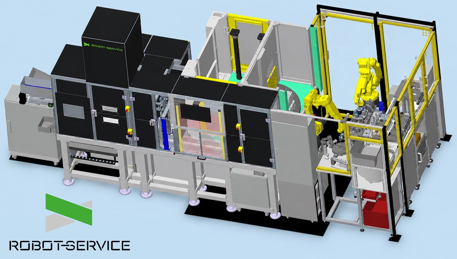
In the implemented solution, we installed a six-axis robot on an external linear seventh axis. The robot tends all four testers in sequence, then returns to the infeed side of the cell, where a separate finished-product output point is also located. One gripper and one reject conveyor are sufficient, and the intermediate transfer nest is eliminated. Here, the seventh axis is a linear track that moves the robot base, rather than an additional rotary joint built into the robot arm.
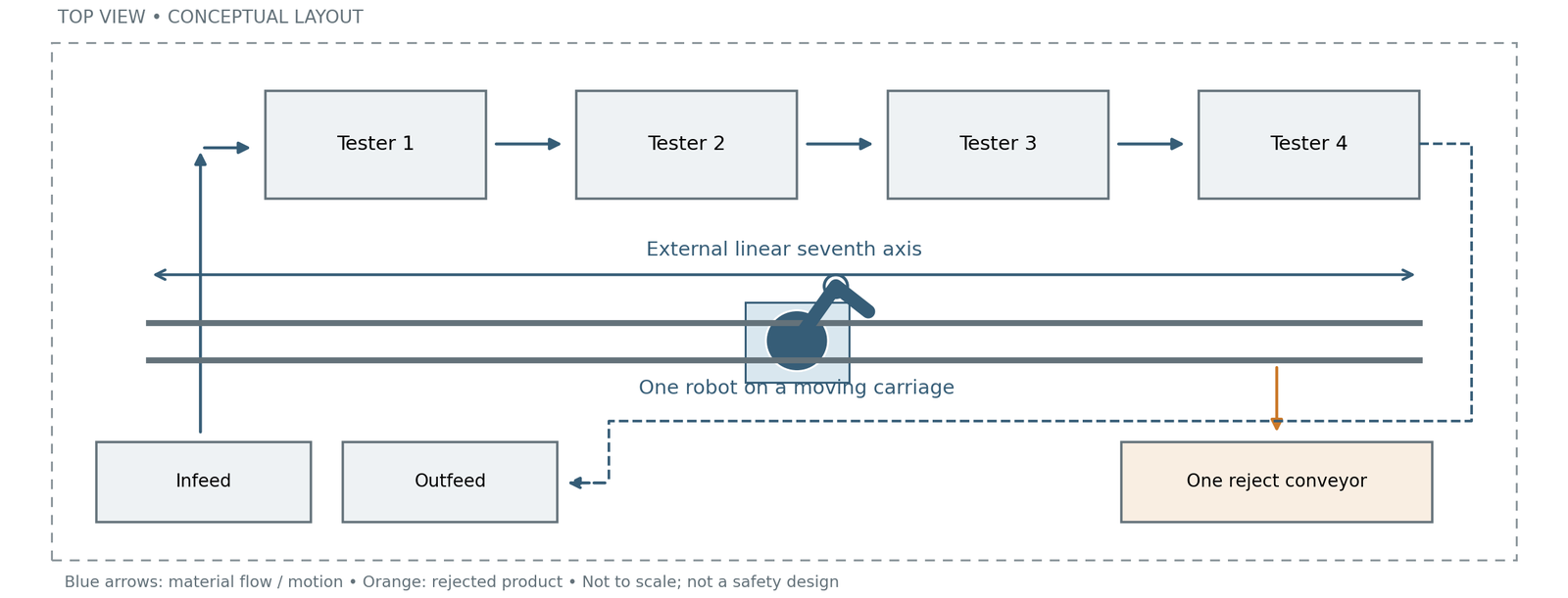
Figure 11 One robot on an external linear axis with infeed and outfeed on the same side
When combining tasks is appropriate
A linear axis can be advantageous when a robot has enough time to serve several stations but cannot reach all the required points from a single fixed position. Extending its workspace can avoid the need for a second robot, gripper and transfer point. Where the product sequence varies, routes between stations can also be organised more flexibly, provided the process and control system allow it.
Two fixed robots offer parallel operation, shorter moves and a larger time margin. The intermediate nest decouples the two handling stages but adds another placement, pickup and status check. The linear-axis solution contains fewer duplicated units, but travel, dwell time after stopping and return time must also fit within the required output interval. A fault in the single robot or its track affects the entire handling process. Nor does the two-robot solution automatically provide redundancy when the process steps depend on one another.
Cycle time and robot utilisation
The cell’s required output interval was 48 seconds: once the line is filled and running continuously, one finished product must leave the cell every 48 seconds. This is neither the total throughput time for one part nor the duration of an individual test. Testing takes place in parallel on different parts at several stations; the robot replaces the part that has completed a given test with the next part. We used simulation to compare the two concepts, examining accessibility and the handling sequence together.
The handling time for each of the two fixed robots was 19 seconds. The following numerical example illustrates the time demand of the linear-axis solution: adding seven seconds for track travel, positioning and return to 19 + 19 seconds of handling gives an active time of 45 seconds. The seven-second value and the resulting 45 seconds are illustrative figures, not results taken from the project’s simulation report. This simplified example does not credit the time saved by eliminating the intermediate transfer.
| Metric | Two fixed robots | One robot on a linear axis |
|---|---|---|
| Required output interval | 48 s / finished product | 48 s / finished product |
| Active time per robot in each interval | 19 s per robot | 45 s, illustrative value |
| Time remaining within the interval | 29 s per robot | 3 s |
| Time-based robot utilisation | 19 / 48 ≈ 40% | 45 / 48 ≈ 94% |
The two-robot system leaves a larger time margin. In the numerical example, the single-robot solution fits within the 48-second output interval with three seconds to spare. This is a narrow margin, so the assessment must also cover tester completion times, reject handling and the complete motion sequence. Higher robot utilisation shows that the same task is performed with less installed robot capacity. It does not, by itself, mean more good parts or better overall equipment effectiveness; its economic benefit here is the lower capital requirement.
Equipment requirements and implementation effort
We compared the two concepts as complete, integrated handling systems. In addition to the robot and its controller, a robot unit includes the support structure, gripper, mechanical and electrical design, robot and PLC programming, communication and robot-side safety integration. Assembly, installation, initial start-up, position teaching, testing and commissioning are equally important parts of the scope. Reducing the number of robots therefore reduced the effort required at several stages of implementation, as well as the equipment purchases.
| Equipment or unit | Two fixed robots | One robot on a linear axis |
|---|---|---|
| Robot and robot controller | 2 units | 1 unit |
| Gripper | 2 | 1 |
| External linear axis | None | 1 |
| Reject conveyor | 2 | 1 |
| Intermediate transfer nest | 1 | None |
| Mechanical support structure | Mounting and support structures for two robots | One robot carriage, track supports and mounting |
| Safety fencing, gate and cell-level protection | Required | Required, with approximately the same scope |
| Testers and common infeed and outfeed functions | Four testers; peripherals required for the task | Same process task and number of testers |
The combined solution required one gripper to be manufactured, one robot to be installed and started up, and one PLC–robot connection to be established. More working positions had to be taught, but only one robot main program and its error handling had to be developed. Control of the product transfer between two robots was eliminated, while integration of the linear axis introduced an additional task. Interfacing with all four testers and verifying the safety of the complete cell remained necessary in both solutions.
The following table illustrates the differences using a five-point engineering assessment scale. A score of 1 indicates lower effort and 5 higher effort. The scores are intended only for comparison within each row; they are not measured labour hours. They cannot be added together or used to calculate a percentage reduction in labour time.
| Work stage | Two fixed robots | One robot on a track | Reason for the difference |
|---|---|---|---|
| Mechanical design | 4/5 | 3/5 | Fewer grippers and peripherals; installing the track requires additional design work. |
| Electrical design | 4/5 | 3/5 | Fewer separate units to connect, but the track drive and cabling must also be provided. |
| Robot programming and position teaching | 5/5 | 4/5 | One main program and error-handling routine; more taught positions and external axis control. |
| PLC programming and PLC–robot connection | 4/5 | 3/5 | One robot connection with no intermediate transfer; the complete process sequence must still be managed. |
| Tester interfacing | 4/5 | 4/5 | Communication and status handling for four testers are required in both cases. |
| Linear axis integration | Not required | Additional task | Coordinating the drive, reference frames, cabling and motion. |
| Safety integration and verification | 4/5 | 4/5 | Fewer robot-side interfaces, but the track and complete cell must also be checked. |
| Assembly and on-site installation | 5/5 | 3/5 | Fewer units to assemble and connect; track alignment is still required. |
| Initial start-up, testing and commissioning | 5/5 | 4/5 | One robot to start up; testing of the complete station sequence and error handling is still required. |
Capital expenditure and return on investment
For the capital items included in the comparison, the single-robot solution with a linear axis required nearly 40% less investment. Taking the two-robot variant as a baseline of 100%, the capital expenditure index of the combined solution is approximately 60%. The comparison covers the robot units and their integration, the linear axis, reject conveyors, transfer nest and fencing package. The testers and the infeed and outfeed peripherals with the same scope in both concepts are excluded from this cost boundary. The ratio does not apply to the complete production system or to other projects.
The difference came from eliminating the second integrated robot unit, one reject conveyor and the intermediate transfer nest, together with the associated reduction in assembly and engineering work, after accounting for the additional linear axis. The gripper is already part of the robot unit, so its elimination was not counted again separately. For the same production requirement, lower capital expenditure can improve returns, but this must be assessed alongside operating and maintenance costs. Higher robot utilisation is not, in itself, a separate financial gain.
Related reading: Return on investment and decision support in industrial manufacturing
Maintenance and lifecycle cost
Robot-Service also examined the maintenance and operating implications during selection. The single-robot solution has fewer robots, grippers and reject conveyors to maintain, and no intermediate transfer nest to inspect. This means fewer units requiring maintenance and fewer potential sources of failure. However, the linear track introduces additional tasks: the condition of the linear guides, drive, lubrication points and moving cables must also be monitored in accordance with the requirements of the specific design.
Higher time-based utilisation of the single robot may mean more intensive use, which can warrant more frequent maintenance depending on the actual duty and the manufacturer’s requirements. However, utilisation is not the same as mechanical loading: the moving mass, inertia, acceleration, motion profile and operating environment all affect wear. Spare time within the cycle may provide an opportunity to optimise motion, but it does not, by itself, demonstrate reduced wear.
This project involved handling lightweight products, and the simulation showed that a time margin remained in the handling sequence. Our engineering estimates considered the loading conditions together with the units that would need to be maintained. They indicated that the additional maintenance effort associated with more intensive robot use and the linear axis was likely to be lower than the maintenance requirements of a second robot unit and its associated peripherals. This is an engineering estimate for the specific application, not a saving verified by long-term operating measurements. The illustrative timing figures presented above do not, on their own, provide a basis for this assessment.
Availability must be considered separately: a failure of the single robot or its track can stop the entire handling process. The two-robot concept does not automatically provide redundancy either, if the test stages depend on one another. Fewer units therefore do not, by themselves, demonstrate higher availability; serviceability, spare parts availability and recovery time also matter.
Our evaluation of a concept also considers its future operation. Robot-Service’s service and maintenance offering supports preventive maintenance planning and equipment upkeep as part of this approach. The maintenance plan must be based on the manufacturer’s requirements and actual operating experience, so that the benefits estimated during design can also be checked in use.
Lessons from the selection process
The implemented solution was based on a combined assessment of geometric accessibility, handling time, equipment requirements and the expected effort and costs over the lifecycle. The linear axis enabled one robot to serve all four testers, reducing the number of units that had to be built, integrated and maintained. The decision was driven by finding a technically suitable and economical solution to the specified production task, rather than maximising robot utilisation.
Common misconceptions in robot selection
The rated payload applies only to the workpiece mass
The gripper and its accessories also load the robot. The permissible mass can only be interpreted together with centre-of-gravity, torque and inertia limits. A product weighing as much as the robot’s rated payload therefore cannot automatically be assumed to be within its handling capability.
Any point inside the workspace can be reached as required
Geometric reach does not establish that the required orientation or complete path is achievable. The required tool position and orientation must be approached and left without collisions, taking account of axis limits and cabling.
Good repeatability is sufficient for every precision task
The application determines whether repeatability, absolute accuracy, path accuracy or a combination is required. In addition to the robot, the gripper, fixture, product and calibration all affect the accuracy of the complete process.
The fastest catalogue specification means the shortest cycle time
In a real cycle, acceleration, payload, path, settling time and peripheral operation all matter. A ranking based on a short test move may change in the actual application.
The robot purchase price is the cost of robotisation
The robot’s price is one item in the investment. The costs of gripping, safety, system integration and commissioning depend on the task, so no universal multiplier can convert the robot price into the total system cost for every application.
A collaborative robot can operate without safety fencing in every application
The necessary protection must be determined from the hazards of the complete application. A sharp workpiece, hazardous tool or trapping point may require additional measures even when a collaborative robot is used.
A high IP rating is sufficient for every special environment
Protection against moisture and dust does not establish suitability for food production, cleanrooms or potentially explosive atmospheres. These must be checked against the documented properties of the specific robot variant and the complete installation.
Checklist before finalising the selection
- We have defined all workpiece variants, pickup positions and process requirements.
- We have checked the total moving mass, centre of gravity and inertia characteristics.
- We have verified that the required tool positions, orientations and complete motion paths are achievable.
- We have assessed cycle time with the actual payload, peripherals and safety functions in operation.
- We have clarified the required accuracy and the effects of process forces.
- We have checked the mounting arrangement, support structure and environmental suitability.
- We have defined the safety concept and the required integration options.
- We have compiled the total capital cost and assessed operating requirements.
- We have established measurable acceptance criteria for operation.
Sound robot selection requires catalogue data to be checked against the requirements of the specific task. Load analysis, verification of the complete motion path and a realistic cycle-time estimate together show whether the selected robot will perform adequately in the finished system. Involving a specialist with practical robot application experience during preparation can help identify uncertainties and avoid costly selection errors.
Selecting the right robot is therefore the result of a system-level assessment. Robot-Service Kft.’s specialists support the process from clarifying requirements through robot selection and cell concept development to implementation. This allows the decision to be based on technical and economic suitability for the specific production task. Related reading: Robot cell design and construction